Explain Different Types of Adder Circuits
Adders in digital Electronics Notes. A combinational logic circuit that performs the addition of three single bits is called Full Adder.

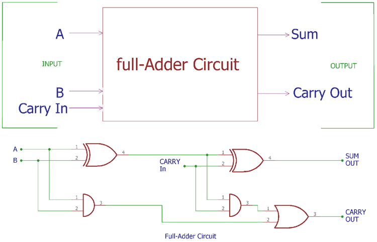
Full Adder Circuit Using Logic Gates
A and B which add two input digits and generates a carry and a sum.
. A binary adder is something which deals with addition of binary numbers. Carry Skip Adder CSkA Carry Increment Adder CIA Carry Look Ahead Adder CLA Carry Save Adder CSA Carry Select Adder CSlA and Carry Bypass Adder CBA are discussed below. There are two inputs and two outputs in a Half Adder.
8-bit and 16-bit Carry Look-ahead Adder circuits can be designed by cascading the 4-bit adder circuit. Half adder Full adder. The half adder circuit has two inputs.
In the full adder the first carry C is always zero when the first add operation starts. There are basically two types of adders. Inputs are named as A and B and the outputs are named as Sum S and Carry C.
The combination of different logic forms to design a full adder. Types of Binary Adder Subtractor Half Adder Full Adder 4 Bit Adder Subtractor Adder Subtractor. The full adder circuit has three inputs.
The circuit diagram of a BCD adder is shown below. Proj 60 256 bit Parallel Prefix Adders. The design of Carry Select Adder consists of multiple pairs of Ripple Carry Adders RCA that generates partial sum and carry.
Binary Adder are two types. To overcome this. Among those three the two bits results in sum and the third bit is for carrybit from the previous.
A Half-adder is an arithmetic circuit that needs two binary inputs and two binary outputs to perform the. Inverting adder circuit is similar to the above inverting amplifier in which the input voltages are given to the inverting terminal and non-inverting terminal is grounded but the difference in Inverting adder circuit is it has multiple inputs at its inverting terminal. Even though this is a complete form of adder circuit these disadvantages needed to be fixed with the modifications in the circuit to achieve the efficient performance of the system.
Parallel binary adders can add n-bits of two binary numbers in parallel. Each group consists of two Full Adders. Ripple-carry adder illustrating the delay of the carry bit.
Proj 64 UTMI AND PROTOCOL LAYER FOR USB20. Some of the characteristics of combinational circuits are following. In this scenario we go in for a full adder circuit which takes in the three inputs.
There are two types of Adder. The circuit which performs the addition of two binary numbers is known as Binary adder. An adder is a device which add up two numbers and produce the result.
Proj 61 Mutual Authentication Protocol. Multiplexers mux selects the final sum and carry output. Proj 63 Low Power Adder Compressors.
These systems designed with the gates are of two types either. In half adder we can add 2-bit binary numbers but we cant add carry bit in half adder along with the two binary numbers. A Binary Adder is a digital circuit that performs the arithmetic sum of two binary numbers provided with any length.
What is Half Adder and Full Adder Circuit. Inverting Adder Circuit Summing Amplifier Working. It produces two outputs sum S carry C.
Adders are basically classified into two types. It is a arithmetic combinational logic circuit designed to perform addition of two single bits. The half adder circuit can only add two numbers.
Each full adder requires three levels of logic. These two circuits can be cascaded to design of adders that can add numbers of n number of bits. Half Adder and Full Adder.
A series of full-adder circuits can be combined to add binary numbers with as many digits as desired. Half Adder and Full Adder. Combinational circuit is a circuit in which we combine the different gates in the circuit for example encoder decoder multiplexer and demultiplexer.
From 10 to 19 decimal numbers both the binary and codes are different. In a 32-bit ripple-carry adder there are 32 full adders so the critical path worst case delay is 3 from input to carry in first adder 31 2 for carry propagation in later adders 65 gate delays. Proj 62 Overlap based Logic cell.
The detailed explanation of the two types of adder is given below. If it is required to considered the carry bit for the next sequence of addition then in that case the half adder circuit will not work. The most basic arithmetic operation is addition.
What is a Hybrid full adder. Mainly there are two types of Adder. A circuit that does accept a carry input is called a full adder Fig.
Different types of Digital systems are constructed from very few types of basic network configurations such as AND gate NAND gate Or gate etcThese elementary circuits are used over and over again in various topological combinations. In this type of Adder the circuit is divided into modules or groups. The half adder can be used to add two numbers only.
Half adder is a combinational circuit which performs the addition of two binary numbers A and B are of single bit. First let us implement an adder which performs the addition of two bits. The output of combinational circuit at any instant of time depends only on the levels present at input terminals.
This Parallel Adder circuit also reduces propagation delay. Proj 59 Bit Carry Look Ahead Adder. A and C which add three input numbers and generates a carry and sum.
The full adder circuit. Proj 66 Controller Design for Remote Sensing Systems. Half Adder Full Adder Binary Parallel Adders BCD Adder Half Adder.
There are two types of adders. Adders are the circuits in digital logic design that are used for performing the addition of binary numbers in computers or any computing devices. The each and every adder is named based on the propagation of.
But in Full Adder Circuit we can add carry in bit along with the two binary numbers. A half-adder circuit does not have an input to accept a carry from a previous place value. A combinational logic circuit that performs the addition of two single bits is called Half Adder.
One is Half Adder and another one is known as Full Adder. Proj 65 5 stage Pipelined Architecture of 8 Bit Pico Processor. The full adder inputs are three and they are the A B the two standard inputs and the Carry C which makes it different from the half adder circuit.

Binary Adder Half And Full Adder Electrical4u

Block Diagram Of Basic Full Adder Circuit Download Scientific Diagram
Full Adder Circuit Theory Truth Table Construction

Adder Circuit Explanation With Circuit Diagram


Comments
Post a Comment